- On June 27, 2025
- In blog
Complete Guide: Types of PCB Connectors
In modern electronic devices, the interconnection between circuit boards is about more than just “connecting” As devices evolve toward miniaturization and greater integration, design engineers face the critical challenge of achieving stable, efficient signal, power, and data transmission within limited space. PCB connectors play a pivotal role in bridging this gap as core components.
They are used to connect different circuit boards, modules, or even devices to ensure signal transmission. In this article, FastlinkPCB will give you a comprehensive understanding of the types, applications, and selection guidelines for PCB connectors to help you become more proficient in PCB design and manufacturing.
As a PCB manufacturer with 15 years of experience, FastlinkPCB specializes in circuit board production and recognizes the importance of electronic components in comprehensive solutions. If you need assistance with connector selection or procurement for your project, please contact us. We will provide professional advice and one-stop support.
What is a PCB Connector?
A PCB consists of numerous electrical components connected by conductive traces and pads to perform circuit functions. However, in many applications, a single PCB cannot operate independently and must be connected to other modules or devices. This is where PCB connectors come into play.
PCB connectors primarily transmit power or signals, enabling the transfer of data or electricity from one point to another. These connections can occur between different sections of the same circuit board or pcb to pcb connector. Regardless of the application, connectors are mounted on the PCB to serve as interfaces for circuit interconnection.
In actual design and production processes, PCBs are rarely hardwired directly to other components or boards. Connectors are typically soldered onto the circuit board during assembly to create standardized, repeatable interfaces. These connectors enable modularity, maintainability, and scalability within complex systems.
Types of PCB Connectors
1.Wire-to-Wire (WTW) Connectors
During the prototype development phase, cables are connected to circuit boards for cable-to-cable interconnections. In this scenario, one end of the cable is fixed while the other end is removable. Permanent connections are typically achieved through crimping or insulated piercing contacts.
Examples of common WTW connectors include S-ATA data cables, flat cables, FDD/HDD/Ultra ATA 66/100 cables, USB cables, and 1394 data cables.
2.Wire-to-Board Connectors (WTB)
Wire-to-board connectors are used to connect wires or cables to circuit boards. The wire connection end resembles wire-to-wire connectors, while the circuit board end uses press-fit or two-piece soldered connectors to complete the interconnection.
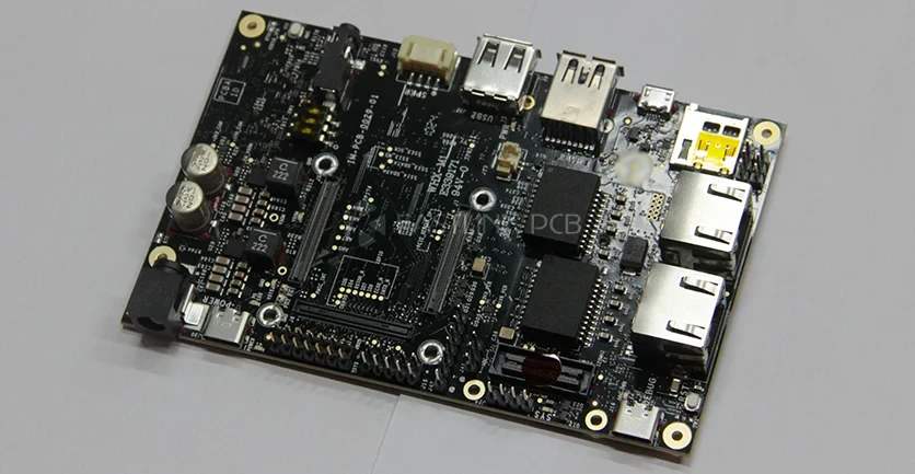
Common wire-to-board connectors include: I/O D-Sub, USB, Mini DIN, Mod.Jace, audio jacks, 1394, and P2*2 interfaces.
3.Board-to-Board Connectors (BTB)
Board-to-board connectors(pcb to pcb connector) are an ideal choice when it is necessary to connect two PCBs without using cables or wires. Compared to traditional cable connection methods, BTB connectors effectively overcome space constraints and are particularly suitable for interconnections in confined spaces. They provide an efficient way to reliably connect circuit boards.
BTB connectors can connect circuit boards in parallel or vertically. When circuit boards need to be stacked, interlayer connectors are typically used. Backplane connectors are another common type of board-to-board connector, typically used in communication and computer systems.
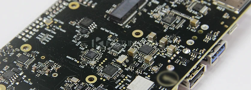
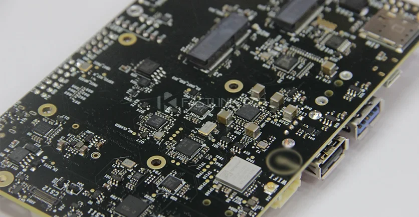
Common board-to-board connectors include memory interfaces (DDR) and expansion slot interfaces (PCI, PCIe, etc.).
How Should You Choose a PCB Connector?
Here are 8 key factors to consider when selecting a PCB connector:
- Product Type: First, determine the type of connector you need. Common types include wire-to-board, wire-to-wire, and board-to-board connectors. Each type has specific application scenarios.
- Pitch: The pin spacing of the connector determines its spatial footprint and compatibility with circuit board layouts. Common pitches include 0.80 mm, 1.00 mm, and 1.50 mm. Ensure the pitch aligns with your PCB design.
- Current (MAX): Each connector has a maximum current rating. Exceeding this rating may cause the connector to overheat or fail. Make sure the connector can support the required current for your PCB.
- Wire Size: The connector’s specifications for wire gauge (AWG) determine the size of wires it can accommodate. When selecting wires, ensure that their specifications align with the connector’s requirements to ensure proper electrical contact.
- Voltage (MAX): The connector’s maximum voltage rating must match the circuit board’s operating voltage. Selecting the appropriate voltage range helps prevent electrical faults and other issues.
- Plating: The connector’s surface plating enhances durability, prevents corrosion, and improves signal transmission efficiency.
- Termination Style: The termination installation method for the connector typically offers two options: surface mount (SMT) and through-hole. Choose the appropriate method based on the circuit board design to ensure stable connections and facilitate assembly.
- TPA Capable: TPA functionality ensures proper terminal positioning and reduces insertion errors. If your application requires higher connection reliability, it is crucial to select a connector that supports TPA.
Using the eight criteria above, you can select the PCB connector that best suits your project requirements. Next, we will introduce some UL-certified connectors from FastlinkPCB, along with their detailed specifications, to help you make a more informed decision.
| Product Name | Pitch | Pitch Current (MAX) | Wire Size | Voltage (MAX) | Plating Style | Termination Style | TPA Capable |
| Zero-Hachi | 0.80mm | 2.5A | 28 to 32 AWG | 30V | Tin | W-to-B SMT | |
| OneBlade | 1.00mm | 2.5A | 28 to 32 AWG | 100V | Tin | W-to-B SMT | |
| Pico-Clasp | 1.00mm | 2.0A | 28 to 32 AWG | 100V | Tin/Gold | W-to-B SMT | |
| Pico-EZmate Plus | 1.00mm | 2.8A | 28 to 30 AWG | 50V | Gold | W-to-B SMT | |
| Pico-Lock | 1.00mm, 1.50mm, 2.00mm | 2.5 to 6.5A | 20 to 32 AWG | 150V, 250V | Gold | W-to-B SMT | |
| Pico-EZmate | 1.20mm | 2.5A | 28 to 30 AWG | 50V | Gold | W-to-B SMT | |
| Pico-Blade | 1.25mm | 2.5A | 26 to 32 AWG | 125V | Tin/Gold | W-to-B, W-to-W SMT, Through Hole | |
| Micro-Lock Plus | 1.25mm, 2.00mm | 3.6 to 4.7A | 22 to 30 AWG | 50V, 250V | Tin/Gold | W-to-B, W-to-W SMT | |
| CLIK-Mate | 1.50mm | 3.0A | 24 to 30 AWG | 100V | Tin/Gold | W-to-B SMT, Through Hole | |
| Pico-SPOX | 1.50mm | 3.5A | 24 to 30 AWG | 250V | Tin/Gold | W-to-B Through Hole | |
| Squba (Sealed) | 1.80mm, 3.60mm | 14.0A | 16 to 24 AWG | 600V | Tin | W-to-W N/A | |
| Micro-Latch | 2.00mm | 4.5A | 22 to 30 AWG | 250V | Tin | W-to-B Through Hole | |
| Milli-Grid | 2.00mm | 4.5A | 22 to 30 AWG | 125V | Tin/Gold | B-to-B, W-to-B, C-to-B SMT, Through Hole | |
| Micro-One | 2.00mm | 4.0A | 22 to 28 AWG | 250V | Tin | W-to-B SMT, Through Hole | X |
| iGrid | 2.00mm | 3.0A | 22 to 28 AWG | 250V | Tin/Gold | W-to-B Through Hole | |
| Nano-Fit | 2.50mm | 8.0A | 20 to 26 AWG | 250V | Tin/Gold | W-to-B, W-to-W SMT, Through Hole | X |
| Mini-Lock | 2.50mm | 5.0A | 20 to 26 AWG | 250V | Tin | W-to-B SMT, Through Hole | X |
| Mini-SPOX | 2.50mm | 4.0A | 22 to 28 AWG | 250V | Tin | W-to-B SMT, Through Hole | |
| RAST | 2.50mm, 5.00mm | 4.0 to 16.0A | 20 to 22 AWG | 250V | Tin/Silver | W-to-B, W-to-W Through Hole, IDT, Pierce | |
| KK Plus | 2.50mm, 3.00mm, 3.96mm | 11.0A | 18 to 28 AWG | 350V, 600V | Tin | W-to-B Through Hole | X |
| CP | 2.50mm, 3.30mm, 4.50mm, 6.50mm | 3.0 to 12.5A | 16 to 28 AWG | 300V, 500V, 600V | Tin | W-to-B, W-to-W Through Hole | X |
| SL | 2.54mm | 3.0A | 20 to 26 AWG | 250V | Tin, Gold | W-to-B, W-to-W SMT | X |
| C-Grid | 2.54mm | 1.0 to 5.0A | N/A | 250V, 250V, 500V | Tin, Gold | B-to-B SMT, Through Hole | |
| KK | 2.54mm, 3.96mm, 5.08mm | 4.0 to 7.0A | 18 to 30 AWG | 250V, 600V | Tin/Gold | W-to-B, W-to-W Through Hole | |
| Micro-Fit | 3.00mm | 10.0A | 18 to 30 AWG | 600V | Tin/Gold | B-to-B, W-to-B, W-to-W SMT, Through Hole, CPI | X |
Final Thoughts
A thorough understanding of the various types of PCB connectors and their characteristics is essential for designing PCBs that operate stably. Selecting the appropriate connectors optimizes space utilization, power management, and energy requirements, thereby enhancing the electronic system’s overall performance.
FastlinkPCB is committed to providing customers with the highest quality PCB connector solutions. Our professional expertise in PCB design and manufacturing enables us to offer customized services to help you design PCB boards with various types of connectors.
If you would like more information about our PCB connector technology or other PCB products, please contact our expert team. They are always ready to provide support and assistance.