- [email protected] Mon-Sun 0. 00-23. 59
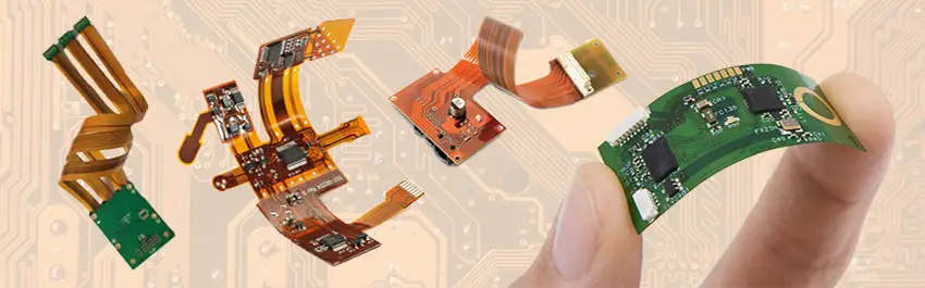
Flexible printed circuit boards (FPCs) are constructed from thin laminates that provide exceptional bendability, tensile strength, and dynamic adaptability. These boards are also known as flex boards, flex circuits, and flexible electronics. FPC assembly involves attaching components to a flex board, a process that shares similarities with rigid board assembly. Our expertise and capabilities enable us to fulfill your specific FPC requirements, as evident on this page.
FPC assembly entails the integration of electronic components onto a flexible printed circuit board. The assembly and soldering processes of FPCs differ from those of rigid printed circuit boards. Due to the FPC’s lack of rigidity, specialized carrier boards are required for secure mounting and handling. Without these carrier boards, basic SMT processes such as solder paste dispensing, component placement, and reflow soldering are rendered impractical.
Therefore, in addition to standard rigid PCB assembly techniques, particular attention must be paid to FPC pre-treatment, supportive carrier boards, and dedicated FPC assembly tools.
Flex boards are typically employed in applications where repeated flexing is a requirement. The assembled components must be able to withstand the demands of their operating environment. Due to their repetitive flexing nature and stringent reliability requirements, flex circuit boards demand stricter cleanliness standards and a lower component count compared to rigid PCBs.
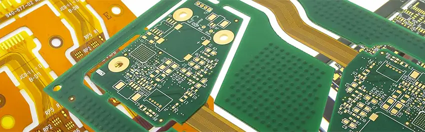
Flex boards commonly utilize polyimide films as their base material, chosen for their notable flexibility and slim profile. When selecting a material, it’s crucial to consider both thermal resistance and electrical conductivity, ensuring the material aligns with the specific demands of the application. This choice is pivotal as it affects the board’s performance under varying temperature conditions and its efficiency in electrical transmission.
The layer count in a flexible PCB is closely linked to its intended use. For dynamic applications where flexibility and movement are frequent, single-layer boards are often the best choice due to their simplicity and flexibility. In contrast, static applications, where the board remains stationary, may require more complexity, with layer counts varying between 4 to 8 layers. This allows for enhanced circuit complexity and improved electrical performance in more demanding scenarios.https://www.traditionrolex.com/28
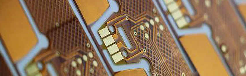
The bend radius is a key characteristic of a flex circuit, directly influencing its flexibility and ability to conform to different shapes. Flex circuits generally have a bend radius ranging from 1 mm to 5 mm. This range is crucial for designers to consider, as it impacts how tightly the board can be bent without damaging the circuitry. The choice of bend radius must be balanced with the overall design requirements, ensuring the board can be integrated seamlessly into its final application without compromising its structural integrity or functionality.
The assembly process of flexible PCBs is intricate, requiring specialized techniques due to their unique material properties and design requirements. Here is a detailed and in-depth look at the key stages of the flexible PCB assembly process:
Flex PCBs are primarily made of polyimide or similar materials, which are more delicate than the rigid substrates of traditional PCBs. The handling of these materials requires care to prevent damage. The material is prepared by cutting it to the required size and cleaning it to ensure a contaminant-free surface for component assembly.
Since flex PCBs are inherently flexible, stiffeners are often applied to specific areas where components will be mounted or where extra rigidity is needed. These stiffeners are typically made of materials like FR4 or polyimide and are attached using an adhesive.
Like rigid PCBs, flexible circuits require drilling for vias and through-holes. However, special care must be taken to avoid damaging the flexible material. After drilling, the holes are plated to establish connectivity between the different layers of the PCB.
Conductive pathways are created on the flexible substrate through a process of printing and etching. This involves applying a conductive material, typically copper, onto the substrate and then etching away the excess to form the desired circuit pattern.
Placing components on a flex PCB can be more challenging than on a rigid board due to its flexibility. Automated pick-and-place machines are often used, but the board may need to be supported to prevent bending or warping. Soldering components onto a flex PCB also requires precision. The flexibility of the board means it can be prone to damage under high temperatures, so controlled soldering techniques such as reflow soldering are often employed.
To provide stability during the assembly process, flex PCBs are often mounted on a carrier board. This board holds the flex PCB in place, facilitating easier component placement and soldering.
After assembly, flex PCBs undergo rigorous inspection and testing to ensure they meet the required specifications. This can include visual inspections, automated optical inspections (AOI), and electrical testing to verify circuit connectivity and functionality.
The completed flex PCBs are then removed from the carrier boards (if used) and prepared for final assembly. This could involve integrating the flex circuit into its final product housing, connecting it with other PCBs or electronic components, and final testing to ensure overall functionality.
Throughout the assembly process, quality control measures are in place to ensure that the flex PCB meets all specifications and performance requirements. This includes checks at various stages of manufacturing and assembly to identify and rectify any issues early in the process.
Since flex PCBs are designed to bend, special considerations during the assembly process ensure that bending does not damage the components or break the electrical connections. The design of the flex PCB will often dictate where and how the board can be safely bent.
Flexible printed circuit boards (FPCBs) are a type of PCB that is designed to be bendable and flexible. This makes them ideal for use in applications where space is limited or where the PCB needs to be able to conform to an irregular shape. However, the flexibility of FPCBs also poses some challenges for assembly.
The base material is the foundation of an FPCB and provides the flexibility and durability necessary for its application. Polyimide (PI) is the most common base material for FPCBs due to its excellent electrical properties, thermal resistance, and flexibility. Other base materials include:
● Polyethylene terephthalate (PET)
● Polyphenylene sulfide (PPS)
● Liquid crystal polymer (LCP)
The choice of base material depends on the specific requirements of the application, such as temperature range, chemical resistance, and flexibility requirements.
The number of layers in an FPCB determines the complexity of the circuit and the number of components that can be mounted. Single-layer FPCBs are the simplest and most commonly used, while multilayer FPCBs can accommodate more complex circuits and higher component densities.
Copper thickness is an important consideration for FPCBs as it affects the current carrying capacity and power handling capabilities of the board. Thinner copper is more flexible but can also limit the current carrying capacity, while thicker copper provides better current carrying capacity but reduces flexibility.
The bend radius is the minimum curvature to which an FPCB can be bent without damaging the copper traces or components. A smaller bend radius indicates greater flexibility but also requires more careful handling during assembly and use.
The solder mask is a protective coating that is applied to the surface of an FPCB to prevent solder from bridging between traces. It is essential for FPCBs as the flexing action can cause solder joints to crack and short circuits to occur.
Surface finishes are applied to the copper traces on an FPCB to protect them from corrosion and improve solderability. Common surface finishes for FPCBs include:
● Organic solderability preservative (OSP)
● Electroless nickel immersion gold (ENIG)
● Immersion gold
The choice of surface finish depends on the specific requirements of the application, such as environmental conditions and component types.
FPCB assembly requires specialized techniques and equipment to handle the flexible nature of the material. Some of the key considerations for FPCB assembly include:
● Pre-treatment: The FPCB may need to be pre-treated to remove surface contaminants and improve adhesion of the solder mask and adhesive.
● Carrier Board: A carrier board is typically used to support the FPCB during assembly and to prevent it from warping or flexing excessively.
● Solder Paste Printing: Solder paste is applied to the copper traces using a stencil. The stencil must be carefully aligned to ensure accurate solder deposition.
● Component Placement: Components are placed on the FPCB using a pick-and-place machine. The placement machine must be able to accurately align and place components on the flexible substrate.
● Reflow Soldering: The solder paste is reflowed in an oven to form solder joints. The reflow oven must be carefully controlled to prevent damage to the FPCB.
● Cleaning: The FPCB is cleaned to remove any residual flux or solder paste.
● Inspection: The FPCB is inspected for defects using visual inspection and automated optical inspection (AOI).
● Testing: The FPCB is electrically tested to ensure that it functions correctly.
Fastlink is a leading manufacturer of flexible PCBs and a comprehensive solution provider for all your flex PCB assembly needs. We offer high-quality FPCB assembly services to engineers and companies worldwide, encompassing component sourcing, flex PCB manufacturing, flex PCB assembly, and testing – all under one roof.
To ensure the exceptional quality of your flex PCB Assembly from Fastlink, we employ state-of-the-art equipment and techniques. Our commitment to excellence extends to rigorous testing, conducted at various stages of the assembly process in accordance with international standards.
Meticulous inspections at every step guarantee flawless completion, preventing errors and ensuring the highest quality standards. We treat you and your products with the utmost respect, just as we do our own. Contact us today to experience the Fastlink difference!