- [email protected] Mon-Sun 0. 00-23. 59
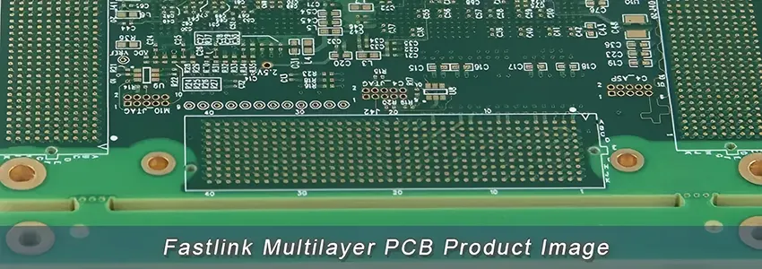
Multilayer PCB consists of three or more copper layers. The core materials utilized in the fabrication of multilayer PCBs include FR4, aluminum, copper, PI, PET, PTFE, and ceramics. Components may be mounted on either one or both sides of these boards. The types of multilayer PCBs encompass multilayer FR4 PCB, multilayer flexible PCB, and multilayer ceramic PCB. Additionally, rigid-flex PCB, HDI PCB, and high-frequency PCB are categorized under multilayer PCBs.
We possess the capability to produce multilayer PCBs with as many as 36 layers. These can have copper weights ranging from 0.5oz to 8oz and widths spanning from 0.2mm to 7.0mm. Furthermore, we offer a diverse range of surface finishes and laminates to cater to our clients’ specific requirements. Our quality management system has been duly certified in accordance with the ISO 9001 standard, ensuring that our products are of trustworthy quality and align with industry standards.
FR-4: This is the most commonly used substrate material for multilayer PCBs. FR-4 is a composite material made up of woven fiberglass cloth with an epoxy resin binder. It offers a good balance of properties: electrical insulation, mechanical strength, and thermal stability.
Copper: The primary conductive material used in PCBs is copper, which forms the traces, pads, and planes. Copper layers are laminated onto the substrate using heat and pressure. The thickness of the copper layer can vary depending on the application and is usually specified in ounces per square foot.
Prepregs are sheets of fiberglass impregnated with uncured epoxy resin. They play a vital role in multilayer PCBs, acting as a bonding agent between the core and the copper layers during the lamination process. When heated, the epoxy in the prepreg flows, sticks to the adjacent layers, and then hardens, creating a solid bond.
This is the green (or other colored) layer often see on PCBs. It’s a protective layer applied over the copper, preventing short circuits, corrosion, and damage. It also provides insulation.
This layer contains symbols, letters, and numbers printed on the PCB for easier component identification and placement. It’s typically applied on top of the solder mask.
● Hot Air Solder Leveling (HASL): A common and cost-effective finish where molten solder is applied to the board.
● Electroless Nickel Immersion Gold (ENIG): A two-layer coating with nickel acting as the barrier to the PCB surface and a layer of immersion gold to prevent the nickel from oxidizing.
● Immersion Silver, Immersion Tin, and Organic Solderability Preservatives (OSP) are other surface finishes used based on specific requirements.
For specific applications, other materials might be preferred:
● High-frequency PCBs: Materials like Rogers or Teflon might be used for their low dielectric constant and loss.
● Thermal Management: For applications requiring better heat dissipation, metal-core PCBs (like Aluminum PCBs) or copper-invar copper (CIC) substrates might be used.
● Flexible and Rigid-Flex PCBs: These use materials like polyimide (PI) for their flexibility.
Adhesives are primarily used to bond different layers of a PCB together, ensuring structural integrity. In flexible PCBs, they help maintain flexibility while providing the necessary bond strength.
The choice of material for a multilayer PCB depends on various factors, including the intended application, electrical requirements, mechanical strength, thermal considerations, and cost.
1. Reduced Size: By routing traces between layers, multilayer PCBs can accommodate more complex circuitry in a smaller physical space. Components can be placed closer together since traces don’t have to work around each other on the same layer. This enables smaller and more compact PCB designs.
2. Increased Routing Density: More layers mean more space for routing traces, allowing greater routing density. This helps optimize trace layouts and facilitates complex routing between components that would be very difficult on fewer layers.
3. Separation of Signals: Different signals with different functions can be assigned to different layers, keeping them isolated. For example, high-speed digital signals can be routed on an inner layer, separated from low-current analog signals on a different layer to prevent interference.
4. Shielding: Since traces and components can be sandwiched between power or ground planes, this provides natural shielding against EMI and also helps prevent crosstalk between traces.
5. Lower Impedance Power Distribution: Power and ground planes can be implemented as complete uninterrupted sheets in between layers, providing very low-impedance power distribution networks.
The fabrication starts with preparing the necessary base materials including copper clad laminates, prepregs, and metal foils. The laminate is the insulating substrate and prepregs are sheets of resin that will bond the layers together.
First, the inner layer circuitry is created on the base laminates through processes of drilling, metallization, photolithography, and etching. This patterns the copper on each inner layer into the desired traces and pads.
The individually processed inner layers are precisely aligned and stacked in sequence. Prepreg sheets are inserted in between each layer. The full stack is laminated under heat and pressure, bonding the layers together.
The outermost layers are processed similarly to the inner layers to pattern the outer layer circuitry. Alignment is critical to ensure vias connect properly between layers.
Small holes called vias are drilled through the entire board to interconnect traces between different layers. The walls of the vias are then metallized to form a conductive path.
Gold or other metal plating may be applied to contacts and edges for solderability and corrosion resistance. Protective solder masks and silkscreens are applied to the outer surfaces.
The boards are cut from the panel and electrical testing validates proper connectivity.
The combination of lamination, precise drilling, and plating of vias enables reliable interconnections through the entire multilayer stack. This manufacturing process allows high densities of traces to be routed efficiently between layers.
HASL is an economical and commonly used finish for PCBs where the board is immersed in molten solder and the excess is removed by hot air knives, leaving behind a thin layer of solder. It offers good solderability but is not ideal for fine-pitch components due to potential uneven surfaces. Over time, the solder coat is prone to oxidation, leading to possible soldering issues. Additionally, the thermal shock during the HASL process can potentially harm the PCB, especially those with high-layer count or small via sizes, making it less suitable for complex and miniaturized circuits.
ENIG is a high-quality surface finish where a layer of nickel is plated onto the copper tracks, followed by a thin gold layer. This combination offers excellent solderability with a stable and protective surface, ensuring a good shelf life and suitability for fine-pitch components. Despite its many advantages, it is more costly than HASL and carries a risk of “black pad syndrome,” a form of nickel corrosion that weakens the solder’s bond to the nickel, potentially leading to joint failure.
Immersion Silver finish involves coating the exposed copper with a thin layer of silver, a more affordable option compared to ENIG, ensuring good solderability. Despite these advantages, the silver layer is sensitive to tarnishing over time and environmental conditions, leading to potential non-conductivity of the pads. Proper anti-tarnish packaging and careful handling during storage and operation are crucial to maintain its effectiveness.
OSP is a cost-effective surface finish, where an organic coating is applied to the copper to protect against oxidation, enhancing solderability. Though economical, OSP is not as durable as other finishes, with a limited solderable shelf life. It is especially suited for surface mount assemblies and Ball Grid Arrays (BGAs) due to its flat surface. However, potential rework may be necessary if there’s an assembly delay, given its limited shelf life and number of reflow cycles.
ENEPIG is a premium surface finish technique that deposits layers of nickel, palladium, and gold onto the copper tracks. This multilayer finish provides exceptional solderability, corrosion resistance, and shelf life similar to ENIG, supporting various assembly methods like gold wire bonding and conductive adhesive assembly. Despite its superior performance characteristics, ENEPIG comes at a higher cost, which should be weighed against the specific requirements of the PCB application.
Stencil printing is the initial phase in multilayer PCB assembly, critical for ensuring the precise application of solder paste to designated areas on the PCB. This process utilizes a stainless-steel stencil with apertures aligned with pad locations on the PCB. A squeegee is used to push solder paste through these apertures, depositing an exact amount on the corresponding PCB pads. Achieving the correct volume and placement of solder paste is fundamental to avoid various solder defects such as solder bridging and insufficient solder, ensuring a robust foundation for subsequent assembly steps.
The pick-and-place process is an automated method where machines accurately position components onto the solder paste-applied PCB. This technique is essential for high-speed, high-precision component placement, promoting the efficiency and reliability of the assembly process. It requires careful coordination and calibration to handle different component sizes and types, ensuring each part is securely and accurately placed for optimal circuit functionality.
Reflow soldering is a crucial phase where the assembled PCB is subjected to controlled heating in a reflow oven, melting the solder paste to form solid solder joints. The process involves multiple stages: preheat, thermal soak, reflow, and cooling, each critically impacting the final solder joint quality. Proper thermal profiling is paramount to mitigate defects like tombstoning, solder bridging, and voids, ensuring reliable and robust solder connections for varied components on the multilayer PCB.
Post-reflow, inspection is conducted to ascertain the integrity and correctness of solder joints and component placement on the PCB. Employing advanced techniques like Automatic Optical Inspection (AOI) and X-ray inspection, this phase identifies and addresses potential issues such as soldering defects and misaligned components. It acts as a quality control measure, ensuring that any anomalies are detected and rectified, contributing to the overall reliability and performance of the assembled PCB.
Through-hole component insertion involves positioning components into drilled holes on the PCB. It can be conducted manually or automatically, depending on the complexity and volume of the assembly. This process is critical for components requiring robust mechanical bonds, ensuring they are securely anchored onto the PCB, enhancing the mechanical strength and durability of the overall assembly, especially for components subjected to mechanical stress.
Wave soldering is a prominent technique for soldering through-hole components on a multilayer PCB. The PCB is conveyed over a molten solder wave, allowing the solder to wick into the drilled holes, forming solid solder joints. This method enables efficient and consistent soldering of multiple through-hole components simultaneously, contributing to enhanced productivity and reliability in the PCB assembly process.
Selective soldering is employed for PCBs with a mixture of through-hole and surface mount components. This technique involves the selective application of solder to specific through-hole components, preventing damage to already soldered surface-mount components. It offers precise soldering for complex multilayer PCBs, ensuring the integrity and functionality of both through-hole and surface-mounted components in a mixed assembly environment.
In the final stages of multilayer PCB assembly, the board undergoes thorough cleaning to eliminate flux residues, preventing potential corrosion or contamination. Post-cleaning, various testing methodologies such as In-Circuit Test (ICT) and Functional Circuit Test (FCT) are applied to verify the PCB’s electrical performance, ensuring it operates as intended in its final application. These steps are crucial for delivering a clean, reliable, and fully functional PCB assembly, reinforcing the quality and longevity of the end product.
| Items | Performance parameter |
| Number of Layers | 4~36Layers |
| Material | FR-4, Ceramic, Flexible, Metal Core, etc. |
| Board Size | 600*770mm( 23.62″*30.31″) |
| Board size tolerance | ±0.1mm – ±0.3mm(5%~10%) |
| Board Thickness | 0.4mm – 5.4mm |
| Board Thickness Tolerance | ±0.1mm – ±10% of thickness of board |
| Copper Weight | 1/3oz – 2O.0oz |
| Inner Layer Copper Weight | 1/3oz – 17oz |
| Min Tracing/Spacing | 3MIL/3MIL |
| Min.Hole Size | 0.1MM |
| Controlled Impedance | 10% |
| Aspect Ratio | 10:1 |
| HDI Capability | 1N1,2N2, 3N3,N4N |
| Min Blind/Buried hole size | 0.1mm(1-18layers) |
| Surface methond | ENIG, OSP, Lead free HASL, Gold plating (hard gold), Immersion Silver, Immersion Tin, Plating Tin, Plating Silver, Carbon Ink. |
Today’s electronics can’t do without multilayer PCBs. These circuit boards are notably smaller, faster, more potent, and increasingly prevalent. As a leading multilayer PCB manufacturer, our rigorous quality assurance process commences immediately upon the receipt of your Gerber files. We can enable the early identification of any potential errors, thereby safeguarding you from expensive errors subsequent to the fabrication phase.
With extensive experience spanning over fifteen years in the fabrication of a diverse array of multi-layered boards, we assure the delivery of products that strictly align with the highest quality standards. Whether you are in search of a prototype or large-scale manufacturing, Fastlink is equipped to provide a customized solution to meet your needs. If you are seeking a supplier, please contact us to learn more about our multilayer PCB manufacturing and assembly services, and understand how they can bring advantages to your electronic project.
We are duly certified with the following accreditations:
● IATF 16949:2016
● ISO 9001:2015
● ISO14001:2015
● ISO13485:2016
● UL
Furthermore, all our products adhere to the IPC & ROHS Standards. It is our continuous endeavor to produce premium quality PCB products.