
- On December 11, 2025
- In blog
LED PCB Guide: From Materials to Manufacturing and Assembly
LED technology has reshaped the modern lighting industry, and at the core of this transformation is the often-overlooked component that makes everything possible—the LED PCB. Whether it’s the lamp on your desk or the massive display screens in sports arenas, the design and build quality of the circuit board play a decisive role in overall performance.
If you’ve ever searched for a solution and wondered where to source circuit boards equipped with LEDs, what you really need is a dedicated LED PCB manufacturer. This guide walks you through every aspect of LED PCBs—from design considerations to manufacturing and final assembly—helping you navigate the entire journey from concept to finished product.
Types of LED PCBs: Which One Should You Choose?
Selecting the right substrate is one of the most important decisions when building an LED circuit board. Each type is defined by the material at its core:
FR-4 LED PCB
FR-4 is the standard material used in traditional PCBs. For low-power LEDs with minimal heat-dissipation needs, FR-4 offers a cost-effective solution and is widely used in everyday household lighting. Although its thermal conductivity is limited, adding a metal frame and tying it to the external environment can significantly improve heat dissipation. FR-4 materials come in different temperature ratings, with Tg values ranging from 135°C to 220°C, so it’s important to match the material to the LED’s actual operating temperature.
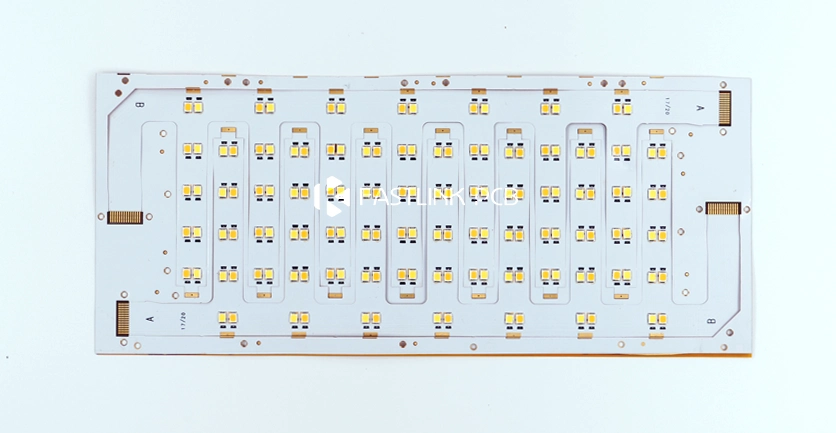
Metal-Core LED PCB
MCPCBs are the go-to choice for high-power LED applications and are typically available in aluminum-based and copper-based versions.
- Aluminum PCBs: The industry standard for most lighting products, aluminum-based boards offer an affordable solution with simple constructions of 1 to 4 layers. With thermal conductivity usually between 1W/mK and 2W/mK, these boards can handle the heat output of standard lighting systems.
- Copper PCBs: Designed for high-performance, high-power LEDs, copper-based boards are commonly used in demanding applications such as automotive headlights. While structurally similar to aluminum boards, their thermal conductivity is several times higher. They can also support a thermal-electric separation design, where LED pads sit directly on the copper base. This allows heat to move quickly and efficiently to the outside environment, achieving thermal conductivity close to 398W/mK.
Ceramic LED PCB
Ceramic PCBs are a strong match for specialized products like photography lights and underwater lighting. Two common types are aluminum nitride and aluminum oxide—materials that differ widely in performance. Aluminum nitride offers around 180W/mK of thermal conductivity, while aluminum oxide provides about 20W/mK. Because ceramic boards require careful handling and may crack during lamination, especially in larger sizes, thoughtful mechanical design is essential.
Hybrid-Substrate LED PCB
Hybrid substrates combine multiple materials into a single PCB to deliver tailored electrical and thermal performance. Examples include ceramic embedded in copper, FR-4 paired with copper, or FR-4 combined with polyimide. These mixed-material boards allow designers to separately optimize circuit routing and heat management, making them suitable for specialized or high-performance applications.
Flexible LED PCB
Built with flexible materials such as polyimide or polyester, flexible PCBs are widely used in LED strips and wearable electronics. Their ability to bend and fold makes them ideal for unconventional shapes and creative lighting layouts. Flexible LED PCBs are also extremely lightweight, offering far greater design freedom compared with traditional rigid PCBs.
How to Make an LED PCB?
While LED PCBs go through many of the same steps as standard PCB manufacturing, the added demands of LED applications—high power, strong heat dissipation, and long-term reliability—mean that several stages require closer control.Most medium- and high-power LED PCBs are built on metal-core materials, typically aluminum. Their production flow differs significantly from that of conventional FR-4 PCB:
- Preparing the Base Material: Aluminum sheets are cut to size and thoroughly cleaned to remove oils and contaminants, ensuring strong adhesion throughout the process.
- Transferring the Circuit Pattern using chemical etching or dry-film imaging.
- Applying the Insulation Layer, typically a thermoset resin loaded with thermal fillers, which creates a structure that provides both electrical insulation and efficient heat transfer between the aluminum base and the copper layer.
- Building the Copper Circuit Layer on top of the insulation through electroplating or other metallization techniques, forming the conductive traces used to mount LEDs and other components.
- Drilling, V-Cutting, and Depaneling: Since aluminum is a metal, special tooling is required, and the process must account for mechanical stress and thermal expansion to prevent damage.
Key Considerations:
Aluminum PCBs place stricter demands on drilling, routing, and surface preparation than FR-4. Careless drilling or depaneling can compromise the insulation layer or introduce mechanical defects. For this reason, manufacturers must have the right lamination processes and precision machining capabilities to ensure the board’s structural and thermal integrity.
LED PCB Assembly Process
SMD LED Assembly Process
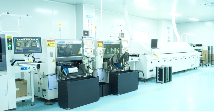
SMD LEDs follow the same SMT workflow used for most modern electronics. Production begins with solder paste printing, where a stencil deposits precise amounts of solder paste onto each pad.
An SPI system then verifies the print quality—checking thickness, coverage, and consistency—because even small deviations can affect solder joint reliability.
Next comes component placement. High-speed pick-and-place machines accurately position each LED, achieving placement tolerances typically within ±0.05 mm.
Once the LEDs are in place, the board enters the reflow oven. As it moves through the controlled temperature zones, the solder paste melts and forms strong, reliable joints. The entire reflow process is fully automated.
The final step is AOI inspection, which confirms proper alignment and verifies the integrity of every solder joint to ensure consistent LED performance.
COB LED Assembly Process
COB (Chip-on-Board) technology mounts LED chips directly onto the substrate, removing the need for traditional LED packaging. Two primary techniques are used: wire bonding and flip-chip bonding.
Wire bonding is the long-established approach, using fine gold wires to connect the chip’s electrodes to the PCB pads.
Flip-chip bonding is a more advanced method where solder bumps are fabricated on the underside of the chip. Through thermo-compression, the bumps reflow and form a direct electrical and mechanical connection to the substrate.
Through-Hole LED Assembly Process
Through-hole LEDs rely on the classic insertion method in which the component leads pass through drilled holes in the PCB and are soldered on the opposite side. This creates a strong mechanical anchor that withstands vibration and mechanical stress, making it ideal for rugged environments. Because the process is simple and the connections are highly reliable, through-hole LEDs continue to play an important role in applications where durability matters.
Where Can I Find LED Circuit Boards?
When sourcing LED circuit boards, the key is to work with a PCB manufacturer that truly understands the unique requirements of LED applications. A capable LED PCB supplier should be experienced with materials like aluminum and copper substrates, maintain strict quality control, and offer SMT assembly and thermal management expertise specifically for LED products.
FastlinkPCB has specialized in LED PCB manufacturing for 16 years. We offer a full range of options—aluminum, copper, FR4, flexible, and ceramic LED PCBs—supported by advanced SMT assembly lines, rapid prototyping, and dependable mass-production capabilities. If you have any questions, we’re always here to help.