- On January 15, 2026
- In blog
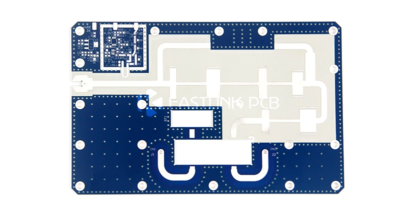
Characteristics and Manufacturing Challenges of PTFE PCB
Let’s be honest: FR-4 is a workhorse, but it has its limits. When you start pushing your signal frequencies into the GHz range, that trusty FR-4 starts to fail. You’ll see signal loss, interference, and performance drops that just aren’t acceptable. If you’ve reached that point, you’re likely looking into Teflon (PTFE) PCBs.
The big draw for PTFE PCB—or Polytetrafluoroethylene, if you want to be formal—is how rock-solid its electrical specs stay, even under pressure. It has a super low dielectric loss, which is exactly what you need for high-speed designs. But here is the catch: PTFE is notoriously difficult to work with. It’s “slippery” and soft, meaning the manufacturing process is a completely different beast compared to standard boards.
Why does that matter to you? Because a great material is useless if the fab house ruins the registration or the plating during production.
We’ve spent years on the factory floor figuring out the quirks of these substrates. In this guide, we’re skipping the marketing fluff and getting straight into what makes PTFE tick and how we handle the manufacturing headaches so you don’t have to.
Dielectric Constant of PTFE PCB
Before we look at anything else, we have to talk about Dk. If you’re designing high-frequency PCB, the dielectric constant isn’t just a number on a datasheet—it’s the heartbeat of your signal integrity. Think of Dk as a measure of how much energy the board material “soaks up” from your signal. A vacuum is the gold standard at 1.0. The higher you go from there, the more energy your substrate stores, which is a polite way of saying it’s going to lag and mess with your signal.
Typical PTFE hits a Dk of around 2.1. That’s about as low as it gets. Because it’s so low, the material doesn’t “rob” your signal or warp its shape as it travels through the copper. You get a clean, crisp transmission from point A to point B.
But here is the real secret: In the RF world, a low Dk is great, but a stable Dk is everything.
Most materials are “moody”—their Dk starts drifting the moment you push the frequency higher. For a precision circuit, that drift is a nightmare because it throws your impedance calculations out the window. PTFE is different. Whether you’re at 1 GHz or pushing into 5G millimeter-wave territory, the Dk stays put.
Why does this matter? Because when you’re building high-end connectors or 5G base stations, you need to know exactly how that board will behave today, tomorrow, and ten GHz from now. That’s the level of reliability PTFE brings to the table, and it’s why we use it for our most demanding builds.
Properties of PTFE PCB Material
We’ve talked about Dk, but that is just one piece of the puzzle. There is a reason engineers call PTFE the “King of Plastics.” It’s not just about one spec; it’s about how this material handles abuse from every angle.
Here is the breakdown of why we use it:
1.Temperature Stability
Most materials fail when things get too hot or too cold. PTFE doesn’t. It handles a massive operating range—staying stable from -454°F all the way up to 600°F. Whether it’s freezing deep-space conditions or high-heat engines, it won’t crack or get brittle.
2.Electrical Performance
It’s a text-book Class C insulator. With a dielectric strength hitting anywhere from 50 to 170 kV/mm, it acts as a fortress against electrical breakdown. If you need reliable circuit protection, this is it.
3.Chemical & Environmental Inertness
You could drop this stuff in aqua regia, and it wouldn’t blink. It resists virtually every chemical solvent out there. Plus, it laughs at UV rays and oxidation. While other plastics yellow and degrade, PTFE keeps its integrity, giving it one of the longest lifespans in the industry.
4.Surface Characteristics
Think about a frying pan, but high-tech. PTFE has the lowest surface tension of any solid material. Nothing sticks to it. With a friction coefficient as low as 0.04, it’s incredibly slick. (Note: This is great for performance, though it’s exactly why we have to use special chemical treatments to get copper to bond to it!)
5.Mechanical Rigidity
Dimensional stability is key. You don’t want your board warping when the temperature shifts. PTFE holds its shape and strength across that wide temperature range we mentioned, ensuring your design stays precise.
Manufacturing Challenges and Solutions for PTFE PCBs
The very things that make PTFE great—its heat resistance and “non-stick” nature—are exactly what make it a headache to manufacture. You can’t just run a PTFE board through a standard FR-4 line and expect it to work. It requires a specialized touch and some heavy-duty equipment.
Here is what we’re up against on the shop floor and how we handle it:
1.Surface Treatment
The biggest strength of PTFE is that nothing sticks to it. But when you need to plate copper or apply a solder mask, that strength becomes a “fatal” flaw. If we just tried standard plating, the copper would literally slide right off the hole walls.
The Fix: We don’t just “clean” the board; we change its chemistry. We use automated plasma gas treatment or sodium-based chemical etching to “roughen up” the PTFE surface at a molecular level. Think of it like sanding a piece of wood before painting it. This ensures the copper and solder mask bond permanently, so you don’t have to worry about delamination later.
2.The Drilling Process
FR-4 is crisp and easy to drill. PTFE? It’s soft, almost like drilling through cold butter, and it’s usually packed with glass fibers. If your drill speed is off, the material smears, leaving you with “tailings” and messy hole walls. In an RF circuit, a messy hole wall isn’t just an eyesore—it creates impedance gaps that kill your signal integrity.
The Fix: We don’t use “off-the-shelf” settings. We’ve developed custom CNC parameters specifically for PTFE. We use specialized drill bits and high chip-load technology to slice through the material and get the waste out fast. The result is a clean, smooth hole that keeps your signal exactly where it needs to be.
3.Thermal Stability
Here is a stat that keeps engineers up at night: PTFE’s Coefficient of Thermal Expansion (CTE) is roughly 5 to 6 times higher than traditional materials. When that board hits the heat during lamination or soldering, it wants to expand—fast. If you don’t handle that expansion, the stress will literally rip the copper away from the substrate or cause “barrel cracks” in your vias.
Our Solution: We don’t just “press” these boards. We use a sophisticated multi-stage vacuum lamination process. By micro-managing the heating and cooling curves, we let the material settle without the drama of warping or cracking. It’s all about precision.
4.Storage & Management
PTFE material can cost you 20 to 50 times more than standard FR4. Not only is it an investment, but it’s also incredibly delicate—think of it as the “diva” of PCB substrates. It scratches if you look at it wrong, and it’s prone to oxidation if left out in the open.
Our Solution: We treat PTFE with kid gloves. At FastlinkPCB, these materials live in a strictly controlled, “dark room” style environment with perfect temperature and humidity. Our workflow is just as tight: once a board is etched, the clock starts. It has to hit the solder mask station within 12 hours. We follow that up with a deep-baking cycle to kick out every last drop of moisture.
Why go to all this trouble? Because when you’re paying for high-performance material, you deserve a final product that’s flawless.
Final Thoughts
At the end of the day, high yields on PTFE boards don’t happen by accident. You can buy the most expensive substrate in the world, but if the shop floor doesn’t have the experience to handle it, you’re just wasting money. Success comes down to one thing: can your manufacturer bridge the gap between “great on paper” and “reliable in the field”?
That’s where we get into the heavy lifting. Turning a tricky material like PTFE into a stable, high-performance product requires a mix of specialized gear, battle-tested processes, and—to be honest—a bit of an obsession with quality control.
At FastlinkPCB, we’ve spent years getting these processes right so you don’t have to worry about them. We take the headaches out of specialty material builds, clearing the path so your design can perform exactly the way you drew it up.