
- On November 2, 2026
- In blog
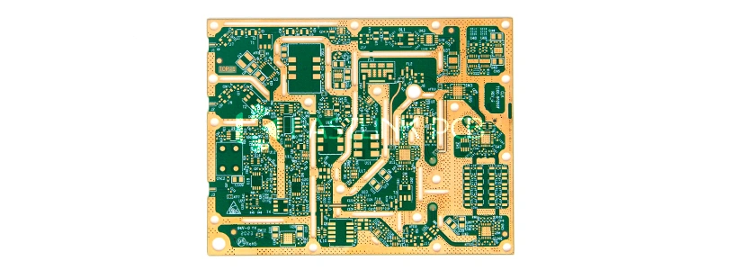
Rogers 3035 PCB Manufacturing
Working on a 77 GHz automotive radar, a base station antenna, or another high-frequency RF project? Odds are the Rogers 3035 name has already come up. The material performs steadily, but it does not machine like standard FR-4. Not even close. Plenty of engineers get a prototype back and find rough hole wall and weak plating adhesion on the Rogers 3035 PCB. The design is rarely the culprit. The manufacturing is.
So what does it take to build a good Rogers 3035 PCB? Here is the rundown.
Why Pick a Rogers 3035 PCB?
Some quick background first. RO3035 is a ceramic-filled PTFE laminate from Rogers, built for high frequency. Its dielectric constant sits near 3.5, its loss stays low, and its performance holds steady across the high-frequency band. That is why it shows up in automotive radar, cellular base station, and microwave link, where signal quality is everything.
The upside is clear. The cost? Processing difficulty. Ceramic filler is hard, and PTFE is non-stick. Put the two together, and nearly every key process step needs a tweak.
Step 1: Drilling
Drilling sounds like simply punching a hole. For a Rogers 3035 PCB, it is the step that tests experience the most. The process differs from drilling glass-reinforced FR-4. Typical parameters look like this:
- Bit material: carbide, 130° point angle
- Surface speed: 200–300 SFM (about 60–90 m/min)
- Chip load: 0.001–0.002 in per revolution
- Stack height: up to 0.240 in (about 6.1 mm)
- Bit condition: new or reground bit preferred
Why so picky? Because ceramic filler chews through a bit fast. A bit for RO3035 usually lasts only 500–1,000 holes. On FR-4, the same bit can drill 2,000 holes or more. Once the bit goes dull, the hole wall turns rough, and every flaw shows up at copper plating. In bad cases, the whole board fails.
The takeaway for production: count every bit use, and never push a worn bit just to save a few dollars. The math never works out.
Step 2: Plasma Treatment in Place of Permanganate Desmear
Drilling leaves a layer of resin smear on the hole wall. Permanganate is the usual fix on FR-4. On PTFE material like RO3035, it falls short.
The right move is plasma treatment before electroless copper deposition:
- Process: oxygen/nitrogen plasma, or CF₄/oxygen plasma
- Purpose: strip resin smear off the hole wall
- Result: a clean, reliable copper-to-copper connection
Think of it as a deep clean for the hole wall. How well this step goes directly shapes the reliability of hole metallization later.
Step 3: Hole Wall Activation and Metallization
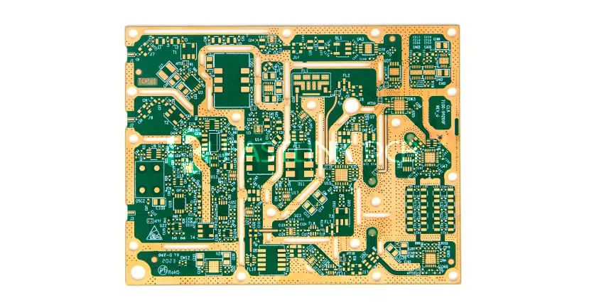
This is the most critical stage in Rogers 3035 PCB manufacturing. Ceramic-filled PTFE has a very inert surface, and electroless copper simply refuses to stick. The hole wall must be “woken up” first. Three methods are common:
- Sodium etching:creates an active surface for the electroless copper reaction. Tetra-Etch is a go-to product in the industry.
- Plasma activation:for a greener route, H₂/N₂ or NH₃ plasma does the job.
- Direct metallization:some fabricators apply a palladium-based process to the plasma-treated PTFE surface.
No single method wins outright. The choice depends on the fabricator’s equipment and process know-how.
Choosing a Surface Finish for Rogers 3035 PCB
Good news: the Rogers 3035 PCB works with all the common surface finishes, so the choice stays flexible.
- ENIG:flat, smooth surface, a fit for high-frequency work.
- Immersion silver:excellent RF performance at a moderate cost.
- HASL:doable, but the surface is rough. Skip it for any design above 10 GHz.
- OSP:low cost, ideal for the prototype stage.
- Immersion tin:good solderability and a flat surface.
Above 10 GHz? Go with ENIG or immersion silver first. The smoother surface disturbs the RF signal less. For prototype validation only, OSP is enough and saves real money.
Is Lead-Free Assembly Safe for Rogers 3035 PCB?
Yes. RO3035 decomposes above 500°C, while lead-free soldering peaks around 260°C. That leaves a huge safety margin. The board fits RoHS-compliant assembly with no special treatment, beyond the routine handling any high-frequency laminate needs.
Final Thoughts
The Rogers 3035 PCB is not an especially hard board to build. The trick is to match the fix to the problem at every step. Get those details right, and the finished board will be reliable.
Planning a high-frequency project? For Rogers 3035 PCB capability and a quote, contact the FastlinkPCB engineering team. The team can offer specific advice based on the stackup and frequency requirement.