- On September 16, 2025
- In blog
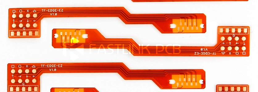
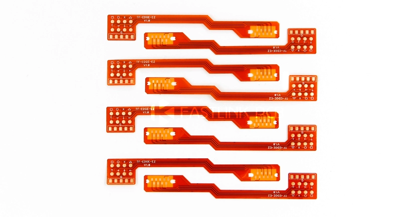
6 Things You Need to Know About Flexible PCB Design
Unlike rigid PCBs, when designing flexible PCBs, you must consider factors beyond circuit functionality—including the board’s bending radius, conductor layout, material selection, and stiffeners. This article outlines six key points to help you balance reliability, manufacturability, and cost during flexible PCB design.
1.Flexible PCB Bend Radius
When designing flexible PCBs, the first consideration is the bend radius. This refers to the minimum radius at which the circuit board can be safely bent without damage. An excessively small bend radius may cause copper trace fractures, layer delamination, or even complete board failure.
The bend ratio is the ratio of the bending radius (R) to the thickness (T) of the flexible circuit. According to IPC standards, static and dynamic applications have different bend ratio requirements:
| Single-layer PCB | Double-layer PCB | Multi-layer PCB | |
| Static | 10:1 | 10:1 | 20:1 |
| Dynamic | 100:1 | 150:1 | Not recommended |
2.Trace Layout Considerations for Flexible PCB Design
- Avoid Sharp Bends: Minimize 90° sharp bends in designs, as these create high stress points at the bend location. Gradual bend angles are recommended to prevent damage.
- Trace Orientation: Traces crossing bend areas should be perpendicular to the bend axis. This ensures even stress distribution during flexing.
- Fine Trace Placement: For traces thinner than 10 mil, position them near the neutral bend axis where stress is minimal during flexing. These traces are more susceptible to fracture.
- Multilayer Circuit Design: In multilayer flexible circuits, staggered trace routing is recommended to enhance circuit efficiency.
3.Material Design for Flexible PCBs: Coverlay vs. Flexible Solder Mask (LPI)
In flexible PCB design, coverlay and LPI are two common protective layer material options.
Coverlay
- Material Composition: Formed by laminating polyimide (PI) or polyester (PET) film with an adhesive layer under high temperature and pressure.
- Function: Primarily encapsulates circuits, providing electrical insulation, mechanical protection, and oxidation resistance.
- Applications: Suitable for areas requiring high-strength protection and frequent bending, such as dynamic bend zones, shielding layers, and stiffener regions.
- Thickness and Color: Common thickness is 1 mil (approx. 25.4 μm). Colors include natural, white, and black.
- Design Considerations: Openings must be created via laser cutting or mold processing. Avoid excessively small openings to prevent damage during fabrication.
Flexible Solder Mask (LPI)
- Material Composition: Formed using photoresist liquids (e.g., epoxy or photoresist resins) through coating, exposure, and development processes.
- Function: Provides basic electrical insulation and prevents solder bridging.
- Applications: Suitable for high-density component areas, particularly in fine-pitch component designs.
- Thickness and Color: Typically 8–12 μm thick, with diverse color options including green, black, white, and yellow.
- Design Considerations: Suitable for static or semi-dynamic applications; avoid use in bending areas to maintain reliability.
Recommendations for Cover Film vs. Flexible Solder Mask
- High-strength protection required: Select cover film, especially in dynamic bending zones or areas needing shielding.
- High-density component design: Choose flexible solder mask, particularly in fine-pitch component areas.
- Combined Use: For complex designs with stringent bending requirements or high density, integrate both solutions. Apply cover film in bending zones and solder mask in high-density component areas.
4.StiffenerDesign for Flexible PCBs
When designing flexible PCBs, certain areas may require reduced flexibility, necessitating stiffener. Common scenarios include:
- Creating flat, rigid surfaces: When providing a stable, flat surface for SMT pad components, stiffeners ensure these components remain unaffected by unnecessary bending during soldering.
- Frequent connector insertion/removal: For connectors requiring frequent plugging and unplugging, stiffeners help reduce pad stress, preventing connector detachment or solder joint damage.
- Components placed in bending zones: When placing components in flexible areas, especially those subject to frequent bending, stiffeners prevent deformation in these zones due to excessive stress.
- Component weight exerting pressure on flexible material: When heavier components are placed on flexible areas, their weight applies pressure to the circuit board. Using stiffeners effectively prevents deformation of the flexible material from excessive pressure.
Stiffeners Design Techniques
- Overlap Requirements: Reinforcements should overlap exposed cover layers by approximately 0.030 inches to effectively distribute stress and ensure stronger interlayer bonding.
- Multiple Reinforcement Design: When using multiple reinforcements, maintain consistent thickness to prevent localized excessive rigidity that could cause stress concentration.
5.Via Design for Flexible PCBs
- Via Placement: Vias positioned in bend zones are prone to excessive mechanical stress, potentially causing plating failure or copper trace fractures over time. Whenever possible, place vias outside bend areas. Ideally, position them where mechanically reinforced by stiffeners. If vias must be placed in bending areas, ensure they are at least 20 mil (approximately 0.5mm) from the bend point and avoid positioning them near the edge of stiffeners to reduce manufacturing stresses.
- Pad-to-Via Alignment: The pad size should be at least 0.010 inches (0.25mm) larger than the via to provide sufficient solder area and ensure stable electrical connection.
- Exercise extreme caution when designing bend zones: If vias are unavoidable in bend zones, always verify the minimum bend radius and overall board reliability. Thus, vias may inadvertently restrict bending flexibility.
6.One-Stop Service for the Design, Manufacturing and Assembly of Flexible PCB
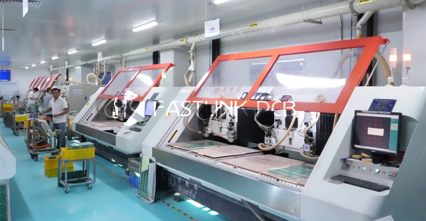
These design details involve numerous aspects. As well as focusing on the functionality of the circuit itself, the manufacturability of the design and the subsequent assembly process must also be considered. To ensure a smooth process, it is advisable to collaborate with a suitable PCB manufacturer from the outset. This prevents manufacturability issues later on and provides professional support throughout the design process, saving you from unnecessary modification costs.
FastlinkPCB offers comprehensive one-stop PCB services, helping you effortlessly navigate each stage from design to manufacturing to assembly. Whether you require flexible PCB design or production, our engineering team, who have 15 years of experience, are here to help. If you have any questions, please do not hesitate to contact us.